Экраны, шторки и другие способы оформления нижней части ванны
Рекомендуем: novamebel05.ru
Рассказываем, как замаскировать нижнюю часть купели и установить защиту от брызг. ШТОРКА для ванны, какую ВЫБРАТЬ?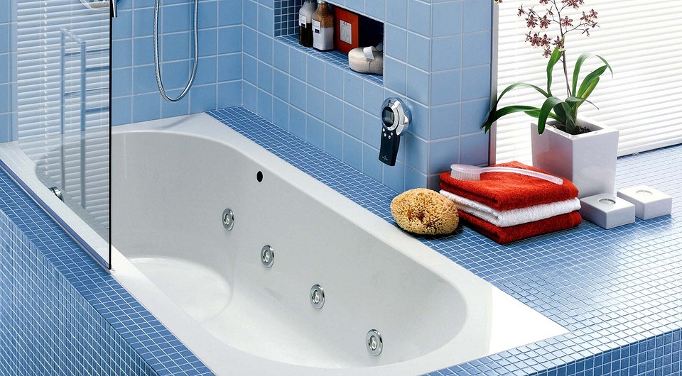
Экраны, шторки и другие способы оформления нижней части ванны
Рекомендуем: novamebel05.ru
Рассказываем, как замаскировать нижнюю часть купели и установить защиту от брызг. ШТОРКА для ванны, какую ВЫБРАТЬ?Что такое акрилатная краска: свойства, применение, разновидности Акрилатная краска — это разновидность лакокрасочных материалов на водной основе. Своими свойствами она похожа на акриловую: разница в
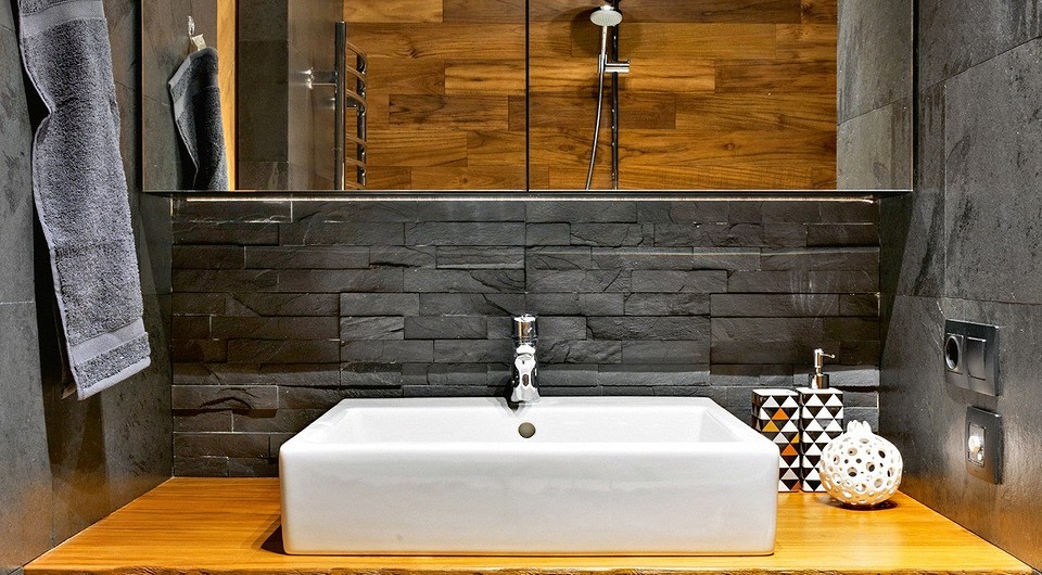
Маленький объединённый санузел, в котором уместились ванна, унитаз и стеллаж для хранения Дизайн этой ванной комнаты выстроен на применении природных материалов: в отделке активно использован
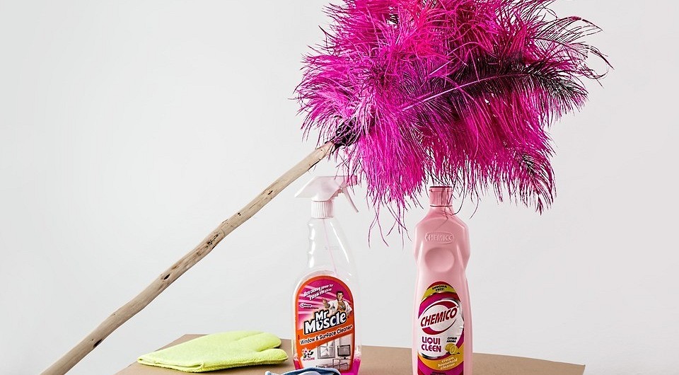
Еще 5 вопросов и ответов об уборке: как помыть пол без разводов и т.п. Продолжаем отвечать на популярные вопросы об уборке квартиры и организации пространства.
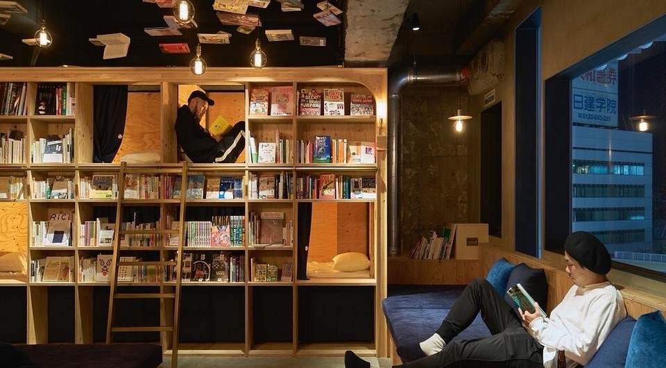
9 неожиданных идей для экономии пространства, подсмотренных в японских отелях Мы заглянули в гостиницы Страны восходящего солнца и обнаружили там немало интересных лайфхаков, которые могут
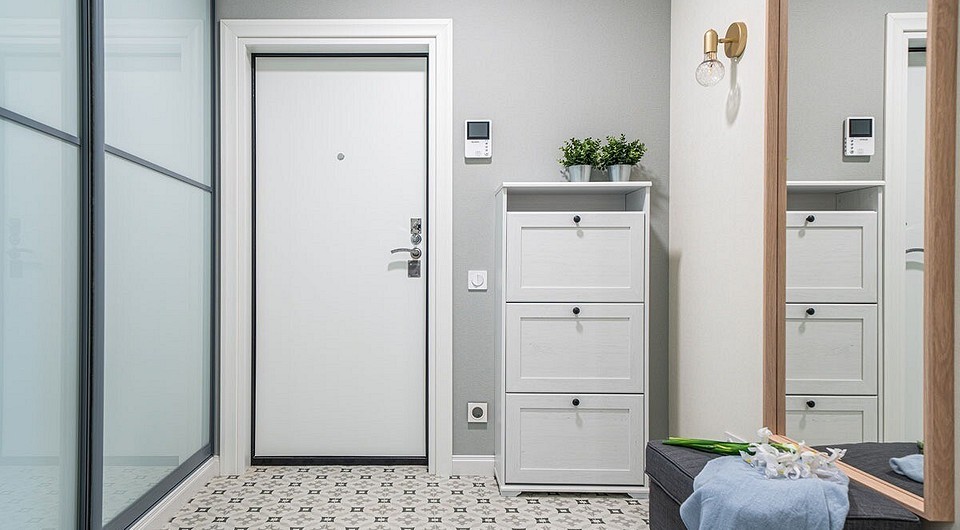
6 современных моделей шкафов в прихожую и коридор: шкаф-купе, угловой, распашной и другие Зеркальный купе, распашной или со скамьей — рассказываем все про подходящие шкафы
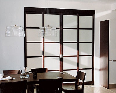
Раздвижные перегородки: типы конструкций, материалы. Раздвижные перегородки их роль в квартире, типы конструкций, материалы для рамы и декоративное оформление вставок. Душевые ограждения из стекла. Раздвижные
Журнал «Идеи вашего дома» №6 (30) июнь 2000 Статьи, обзоры, советы специалистов из журнала «Идеи вашего дома» №6 (30) июнь 2000 Что связать? Обзор Журнал
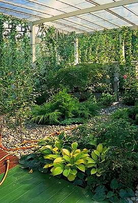
Сад, который живет на крыше Сад на крыше в подмосковном Троицке схема устройства, алгоритм создания и обзор использованных материалов. Сады на крышах. В гостях у
6 простых способов сделать квартиру образцом стиля Хотите получить интерьер, как с обложки? Тогда воспользуйтесь этими приёмами. КАК СДЕЛАТЬ ПАРИЖСКИЙ ИНТЕРЬЕР У СЕБЯ ДОМА. ДИЗАЙН